|
|
|
Introduction
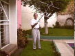
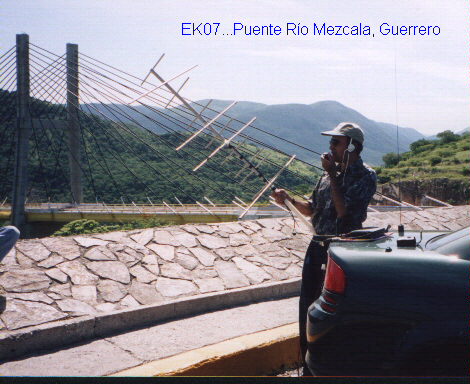
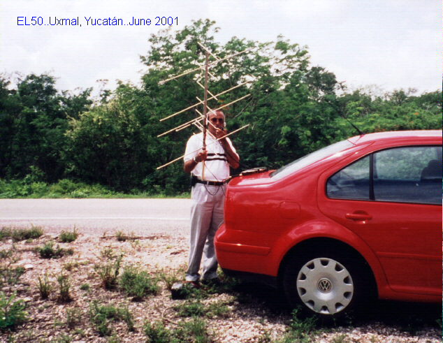
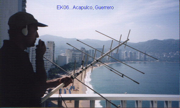
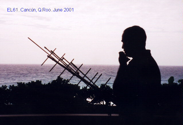
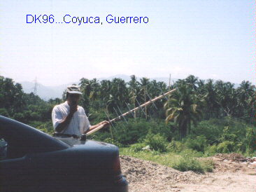
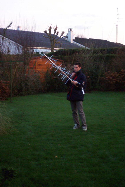
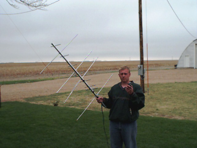
Since it is very difficult to get a commercial VHF-UHF portable antenna in my town, I decided to build a homebrew antenna as I did it in the past with most of my old HF and VHF antennas. My personal commitment was to get it ready for my holidays in Cancún (May 2 to May 8, 1999) in order to operate from the grid locator EL61 using the AO-27 satellite. The antenna performance was excellent and a lot of satellite contacts were made during my stay in Cancún and surrounding areas. Since then I have used it from my home and every time that I have a chance to be out of my home grid locator (EK08mu). In 1999: EK09, EL00 and EL61; in 2000: EL60 and EL61; in 2001: EL61, EL50, EL51, EK06, EK07 and DK96; in 2003: EL61, EL60, EK58 and EK68.
I have succesfully tested this antenna with the satellites AO-27, SO-35, UO-14, FO-20, FO-29, AO-10, SO-50, AO-51 and lately with the ISS...please see the updates and photos below.
Software
The GWBasic software program that I used to design my double Yagi-Uda for VHF and UHF was developed by Guenter Hoch, DL6WU. It is available for download in the following link (80 kB):
Download Yagi-Uda design program by DL6WU
In case you get a password or login request to download the program, please let me know by e-mail..I will send the compressed file directly to your e-mail address. Sometimes the server of your Internet provider rejects the download request.
In order to use this program please follow these instructions:
1. Decompress all files contained in dl6wu_ant.zip into a new folder in your PC.
2. With the windows explorer try to open the file Antdl6wu.bas
3. If a dialog box appears (Open with...) asking you for the program to open it, click in "Other..." and then select the file Gwbasic.exe (which is available in the new folder that you created), then click in "Open" and finally click in "OK".
4. The program should be running now within Windows 95, 98, 2000, XP or NT in a separate window. Please type "Y" just ahead of the question Y/N ? and then press the Enter key. You are in; just follow the instructions and type in your design parameters.
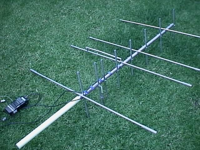
Construction Details
Assuming that you have downloaded the program and it is running properly, what I can share with you (just to save time) are the program results for the specific parameters and material that I had available at home:
REMARKS: All dimensions are in millimeters, all elements are made of aluminum pipe, R=reflector, D=driven, D1 to D6=directors, all spacing between elements is from center to center, elements are mounted over the boom (not through the boom) and they are not isolated to the boom.
I used a teflon rod (430 mm long, 100 mm inserted into the boom edge) as arm/hand support...you can use whatever you have -non conductive of course-.
I used those aluminum pipe diameters because they were available at home, but I strongly recommend you to use thinner pipes (perhaps rods) to make a not so heavy antenna...your arm will thank you in case you like to have long radio contacts. If you do so, do not forget to re-calculate with the actual elements and boom diameters.
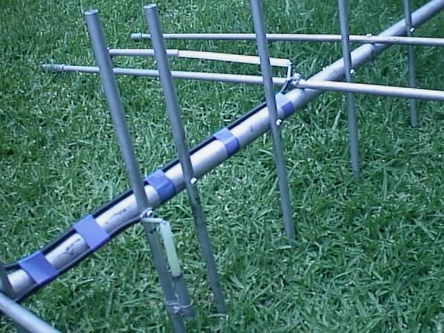
The Gamma Match
Now let´s go to the "difficult" part...the matching between coaxial cable and feed point of the driven elements. Since this is a portable antenna to be used very close to the transceiver, I decided to ignore the losses of the normal BELDEN RG58 A/U coax cable because I installed just 1200 mm of coax between radio antenna connector and each driven element.
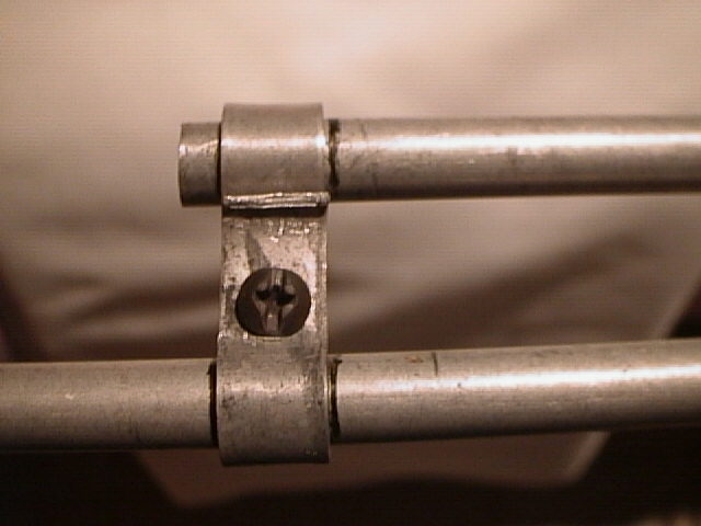
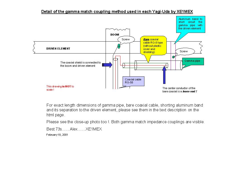
I decided to follow the old and problem free matching method known as gamma match. I have always used it with excellent results, and because I do not install any kind of additional capacitors but I use a bare piece of RG8 or RG213 or RG214 as coupling capacitor which is inserted into an small piece of aluminum pipe. This pipe has an aluminum band which makes the connection between the sleeve and one arm of the driven element. The bare coax means a piece of coax cable without the external plastic cover and without the shield screen...well, I think it is better to see these pictures which tell you more than a thousand words:

 (Feb.18, 2001): The most frequently asked question from the friends that have duplicated this antenna is related to the gamma match. You asked for it many times, so...if you need a simple drawing please click here or in the thumbnail:

Of course you can use any other matching method, but in case of the gamma, here is some data that will save you time:
In case you want to do a fine adjustment to the SWR and assuming you have the proper SWR meter, look for minimum inserting or extracting the bare coaxial part and/or moving back and forth the shorting band.
The Reward
Well, after so much effort the good news...if you duplicate the described antenna, I can guarantee that you will get an SWR of less than 1.3:1 in both center frequencies and not more than 2:1 in the band edges.
I could not measure the front gain but it should be close to the theoretical; anyway, just aim your beam to the AO-27, SO-50, AO-51 or the ISS and I am sure that you will be satisfied with its performance.
Ok, as you see I did not write anything about the diplexer. It is just because I use two radios. I am going to build a diplexer soon; if it works as expected I will publish here the circuit diagram and its construction details.
The Diplexer....I did not build it up to now, but I got an interesting and promising information to build one. Please go to the website of Lee Devlin, K0LEE which contains the Microduplexer designed by Chuck Duey, KI0AG.
I hope you enjoy the construction of this antenna as much as I did.
73 de XE1MEX....Alex
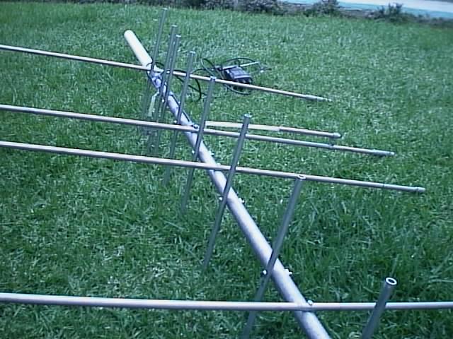


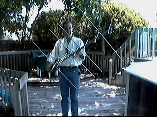
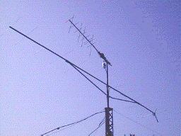
May, 2000....The same antenna above described is now installed at the top of the tower replacing the helical antenna which is now down for repair. The antenna is at a fixed elevation of 30º but installed in a second rotor to have control of polarity...the results are quite good...you should try this mode too, just for fun or to have a cheap way to access the AO-27, UO-14, AO-10, SO-35, FO-20 and FO-29 satellites !!. Sorry, I forgot to tell you that finally I did not built any diplexer...I just bought a Diamond MX-72D which is installed below the rotor and properly protected against the weather in a plastic bottle. In that way I have just one coaxial cable feeding both yagis. See the picture at the bottom of this page.
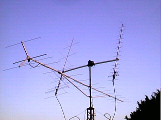
June 4, 2000: I made my very first contacts through FO-20 and FO-29 using the array shown in the photo at the bottom of this page. The homebrew yagi is also working fine for the reception of all digital satellites. I think that working 5 different satellites with the homebrew portable yagi is not bad... of course you can add elements to get extra gain feeding your particular parameters to the design program.
August 20, 2000: I made my very first satellite radio contacts through AO-10 using ONLY my cross yagi as shown in the photo at the bottom of this page (the 16 ele horizontal yagi was not used). It was another milestone for my homebrew yagi. Although the distance to the satellite was "short" (about 8000 kilometers), it was exciting to communicate via AO-10 with just 20 watts output plus 8 elements in the UHF uplink and receiving with just 4 elements in the VHF downlink. The transceiver used was my ICOM IC-706 MKIIG. What else can I say about the home made cross yagi ?...You should try it...its cheap, portable, easy to build and it works !!.
Just for your information: During year 2000 I had 554 succesful satellite radio contacts using this antenna via AO-10, UO-14, AO-27, FO-20, FO-29 and SO-35.
December 2013:....This webpage is now rather old, some of the mentioned satellites are not anymore in operation (SO-35, AO-10, UO-14, FO-20), there are new ones too (SO-50, VO-52 and ISS in the repeater mode) but the most important fact is that this design is proven to be functional and giving satisfactory results !.
Finally, I really appreciate the comments, remarks and kind words of the following radioamateurs that have built a copy of the cross yagi with full success....thank you very much to all of you !!: SP8UFX, XE2ARF, 9Z4DZ, ZL2GVA, ZZ2UHT, YD3RCJ, KF6WCH, KF6PHX, DF8GH, VE1EJM, KK5UFO, IZ5DWF, TI2CPQ, ZZ2NGB, WP4NAL, N0YK, F4DMM, VE2WHZ, 9A5YY, N0YOX, K0KN and EA8AKQ. Thanks a lot to all not mentioned here but I know that they also have built antennas for other frequencies based on the design shown on this page.
Very special thanks to Mr. Guenter Hoch, DL6WU for his attention, patience and useful information shared with me by e-mail.
Your comments will be appreciated: xe1mex@yahoo.com


This page has been visited 

 times since July 24, 2009.